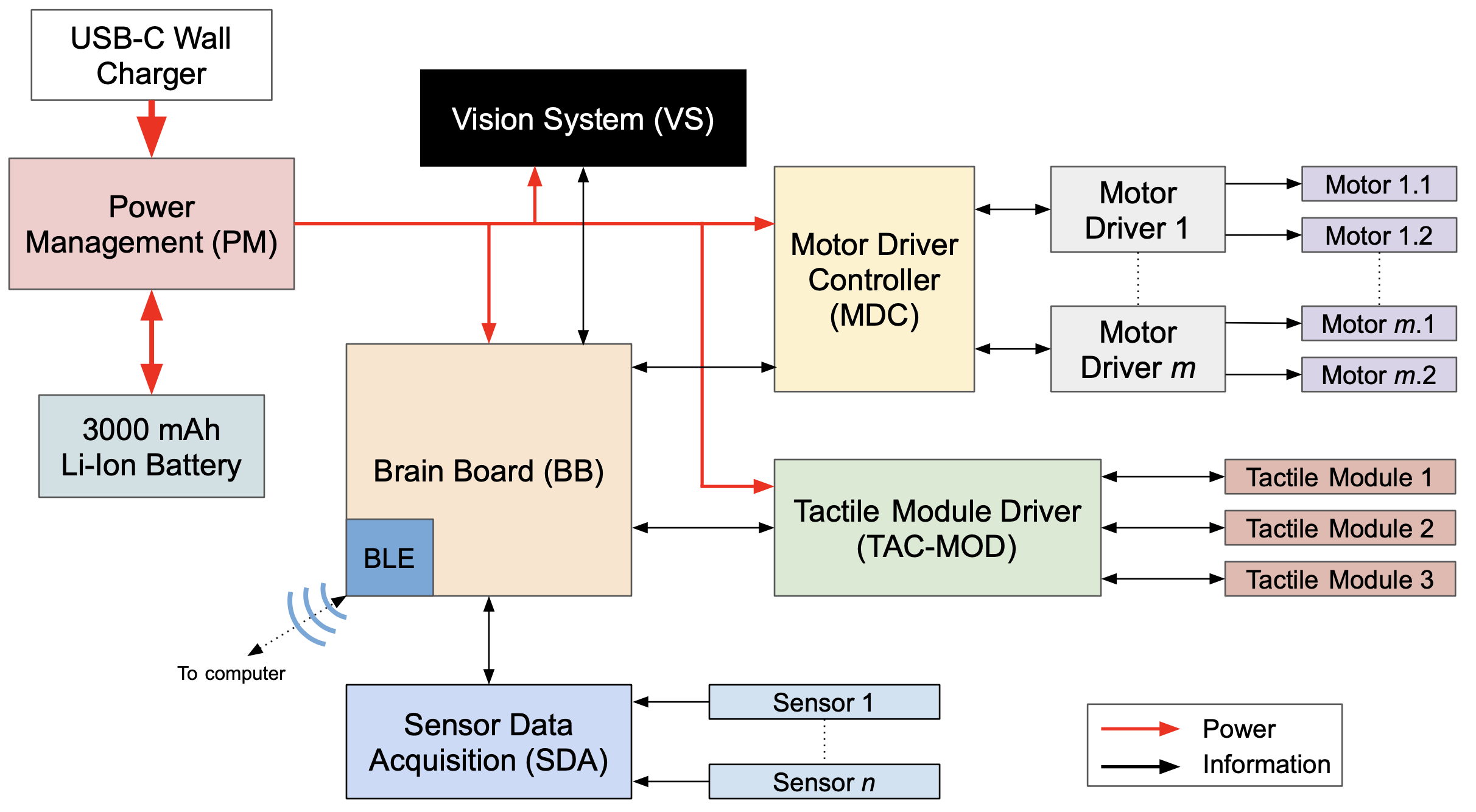
We've organized the embedded electronics according to the logical topology shown below.
Power Management
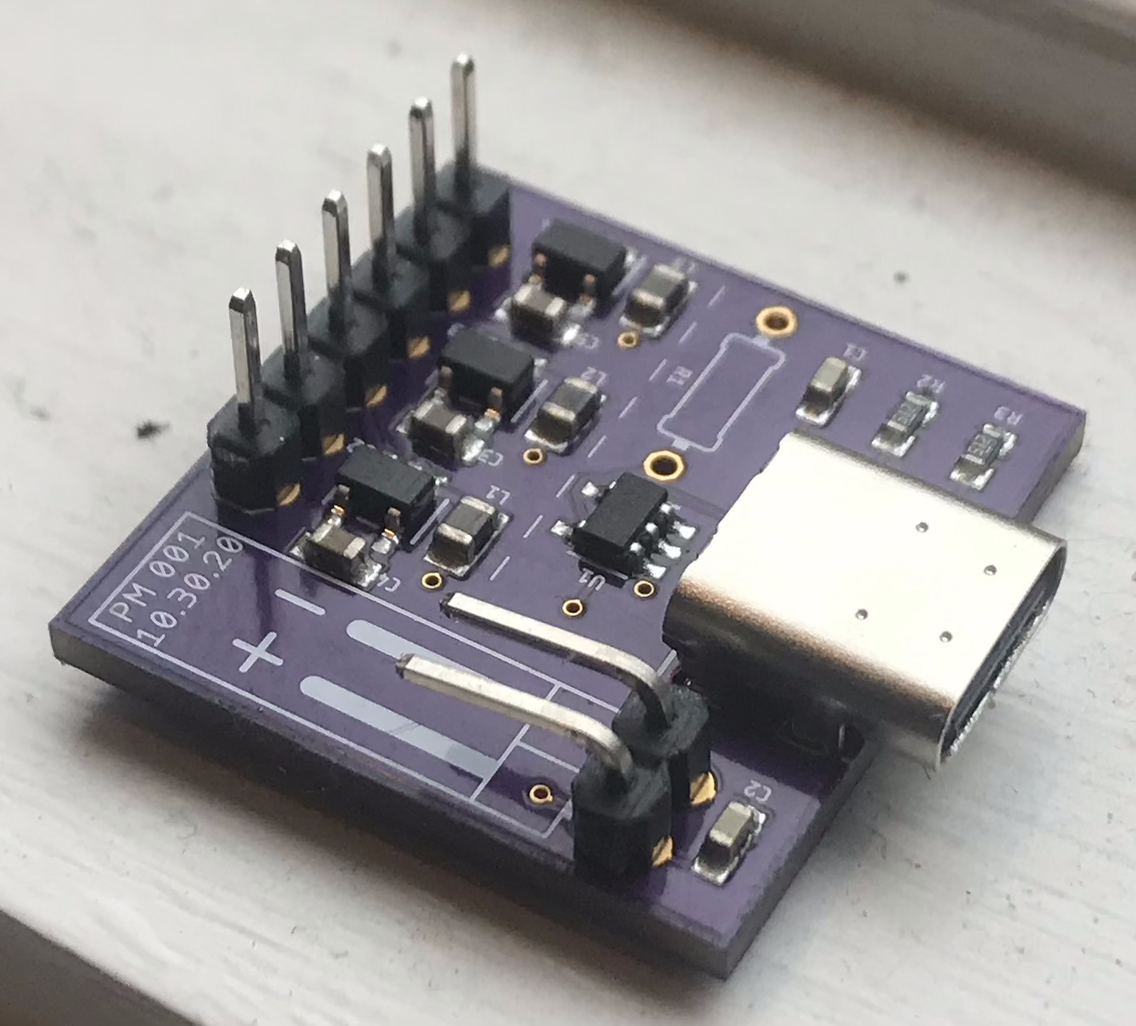
This module has two functions: 1) receive power from the wall and use it to charge the on-board battery, and 2) buck / boost the battery voltage to the various voltage levels required by the other modules. Additionally, this module is responsible for monitoring the temperature of the battery, the current discharge through the system, and the battery voltage, all of which helps to prevent catastrophic brown-outs and meltdowns. All of these things are really monitored by the microcontroller though, since the PM board isn't capable of digital processing on its own.Brain Board
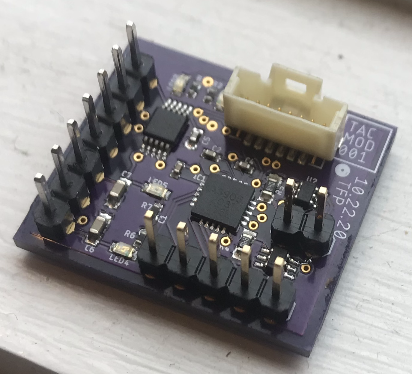
Tactile Module Driver
This module is responsible for driving the tactile feedback unit, which mounts on the user's finger to provide tactile stimulus in two forms: skin-stretch and vibration. For more information on how the tactile module works from a mechanical standpoint, check out its designated page under the "How it works" section of this website. The 20-QFN IC on the board is an A3906 which drives the two DC motors that provide skin-stretch feedback. The 10-VSSOP IC is a DRV2605L which drives a linear resonant actuator mounted on the underside of the tactile module. All the LEDs on the board are just for fun, and probably won't make their way to the final embedded board.Sensor Data Acquisition
No picture associated with this one...yet. This circuit is responsible for reading all of the sensors on the glove and forwarding that data to the brain board in a convenient format. There are two main categories of sensors that are used in the glove: those that measure joint angle values, and thus serve the hand-tracking functionality of the glove; and those that serve to close the control loops on the various motors employed in the force- and tactile-feedback modules.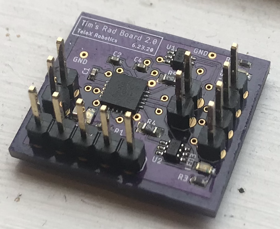
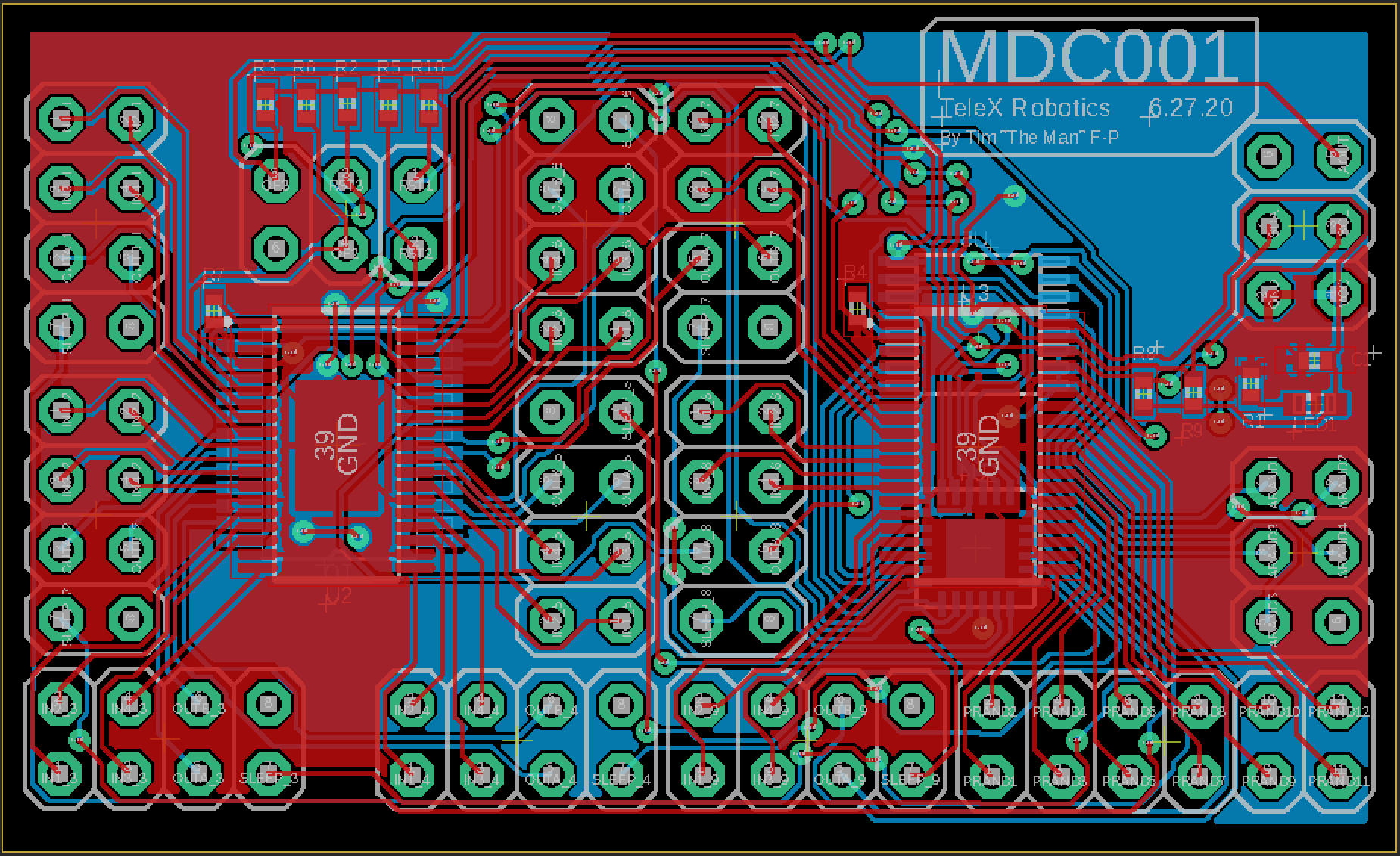
Motor Driver
As far as embedded modules go, this one is about as low-level as it gets. Used to drive DC motors, this board lives one step removed from the mechanics of the glove. It is capable of converting digital signals into appropriate drive voltages for up to two brushed motors and for monitoring the current drawn by each motor. Additionally, it has a low-power mode which enables the glove to save power any time the motors aren't actively being driven. The heart of this module is an A3906 IC, the 20-QFN chip shown in the picture to the left.Tactile Module Driver